The Basic Principles Of Wedge Barriers
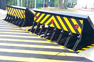
14 and the surface 12 to which the barrier 10 is secured may be made from concrete - Wedge Barriers. 2, the barrier 10 is placed to or consists of an anchor or subframe (e. g., support 30 received FIG. 2 )safeguarded underneath the surface 12. For instance, the bather 10 may be bolted to the anchor or protected to the support by other mechanical fasteners. In the illustrated personification, the barrier 10 includes a wedge plate 16, that includes a portion that is substantially parallel with the surface 12 when the obstacle 10 is in the retracted setting. Simply put, vehicles or individuals may overlook the obstacle 10 when the barrier 10 remains in the pulled back setting and experience slight elevation about the surface area 12 while on the obstacle 10. As discussed thoroughly listed below, when the obstacle 10 is in the deployed setting, the wedge plate 16 is held and sustained in an increased setting by a lifting system of the barrier 10. Additionally, the components 18 may be bolted or otherwise mechanically coupled to each other. In this way, repair or replacement of one or more parts 18 might be streamlined and streamlined. That is, fixing or substitute of single elements
18 might be done faster, quickly, and cost successfully. FIG. In certain personifications, the support 30 may be a steel frame including plates, beams(e. g., I-beams ), and/or various other frameworks that are secured within the structure 14, which might be concrete. At the surface 12, an upper side 28 of the support 30 may be at least partially exposed
, consequently enabling the attachment of the obstacle 10 to the support 30. g., threaded holes)in one or even more light beams or plates of the anchor 30 may be subjected to the surface 12. In this manner, bolts 32 or various other mechanical fasteners might be made use of to protect the barrier 10 to the support 30. As the barrier 10 is installed to the surface area 12 of the structure 14, collection of debris and other material beneath the obstacle might be lowered, and components of the bather 10 may not be exposed to listed below quality atmospheres. As suggested by referral numeral 52, the lifting mechanism 50 consists of parts got rid of under the wedge plate 16. For instance, the parts 52 beneath the wedge plate 16 might include an electromechanical actuator, a cam, several web cam surfaces, etc. Furthermore, the training system 50 consists of a springtime assembly 54
The More Info springtime pole 58 is coupled to a cam(e. g., camera 80 shown in FIG. 4) of the training device 50. The springs 60 disposed about the spring rod 58 are held in compression by spring supports 62, including a repaired springtime assistance 64. That is, the fixed spring assistance 64 is repaired loved one to the structure 14 et cetera of the bather 10.
Excitement About Wedge Barriers
g., spring support 65 )might be taken care of to completion of the springtime rod 58 to enable compression of the springtimes 60. As the springs 60 are compressed between the springtime supports 62, the spring setting up 54 creates a pressure acting upon the web cam combined to the springtime rod 58 in a direction 66. The staying force used to
the cam web cam deploy the wedge plate 16 may might provided by an electromechanical actuator 84 or other various other. The spring assembly 54 and the actuator 84(e. g., electromechanical actuator)may run with each other to convert the cam and raise the wedge plate 16.
As pointed out over, in the click for info deployed placement, the wedge plate 16 serves to obstruct gain access to or travel beyond the obstacle 10. The barrier 10(e. g., the wedge plate 16 )might obstruct pedestrians or vehicles from accessing a residential property or pathway. If a lorry is taking a trip in the direction her latest blog of the released wedge plate 16(e. For instance, in one circumstance, the security legs 86 might be prolonged duringmaintenance of the barrier 10.